Light Scattering by Ice CrystalsA possible upcoming project involving the Manchester Ice Cloud Chamber (MICC) will investigate the light scattering properties of ice crystals. As light waves strike an ice crystal, they can be deflected and travel in a different direction. This scattering direction is not always the same, but over time, with many such light scattering events, a general scattering pattern (scattering phase function) is produced (Fig. 1). The nature of this pattern is determined by the ice crystal’s size and shape and also on the wavelength of incident light. The crystal’s size and shape are in turn determined by the environment in which they are growing; crystals grown at different temperatures for example have different shapes (habits) as shown in the morphology diagram (Fig. 2).An understanding of the scattering of light by ice crystals is important in many areas. Firstly, correctly knowing how much of the incoming solar radiation is reflected back into space has important consequences for studies of our changing climate. Clouds containing crystals of a type which reflect a lot of this radiation (high albedo clouds) can contribute a net cooling effect, acting to counter the warming effect of the greenhouse gases, and is therefore an important area to understand. Knowing how the scattering phase function varies with crystal cloud type will allow the validation of scattering models used in climate studies.This work is also important in the development of the use of light detection and ranging (LIDAR) technology. A LIDAR is a form of radar which emits a beam of light into clouds of shorter wavelength (infrared, 1.5 µm) than most conventional radars (see the Chilbolton weather website for some further reading). The beam is scattered by the cloud particles, and what is returned is used to infer cloud properties. There is uncertainty in the scattering signal produced by ice clouds and a better understanding of how the light is scattered by different crystal habits will help improve the use of the technology. An additional uncertainty comes from the use of 1.5 µm light which is readily absorbed as it travels from and back to the LIDAR through the atmosphere. Using this wavelength in the laboratory studies can also help identify the extent that this is likely occurring in the field.Of particular interest in relation to studies of climate change is the effect that ice crystal aggregates have on scattering. Studies (e.g. Connolly et al., 2005) have shown lots of aggregate particles (long chains of connected crystals) in the anvils of thunderstorms, in particular, the aggregation of horizontally aligned plate crystals which act like small mirrors and generate highly reflective clouds. Such storms and associated anvils are situated in equatorial regions, where the greatest input of solar radiation to the Earth’s heat system occurs, and where it is thus particularly important to understand the scattering properties of such ice clouds. The aggregation section of this website contains further information on this.The MICC facility allows the production of crystals with a wide range of sizes and habits for examination, and uniquely, the production of aggregate particles, thanks to its 10 m height, which provides the fall-time for crystals to stick together. A multi-wavelength tuneable laser will provide a high powered light source to enhance the scattering signal-to-noise ratio, also allowing a quick (<1 s) determination of the scattering phase functions of the crystals. Such rapid measurements are necessary as the properties of the cloud passing quickly through the scattering chamber will not remain constant, e.g. particle concentrations and size distributions will change with time.Experimental procedures will generally involve generating a crystal cloud with desired properties, which will then be introduced to a motorised scattering chamber (Fig. 3). A light source shining into the scattering chamber will interact with the cloud, and the resulting scattering phase function will be measured. The constituent cloud particles are measured with the CPI for later comparison with the scattering phase function.References and other readingConnolly, P. J., C. P. R. Saunders, M. W. Gallagher, K. N. Bower, M. J. Flynn, T. W. Choularton, J. Whiteway, and P. Lawson, 2005: Aircraft observations of the influence of electric fields on the aggregation of ice crystals. Quart. J. Roy. Meteor. Soc., 131, 1695–1712.Heymsfield, A. J., and G. M. McFarquhar, 1996: High albedos of cirrus in the tropical pacific warm pool: Microphysical interpretations from CEPEX and from Kwajalein, Marshall Islands. J. Atmos. Sci., 53(17), 2424–2451.McFarquhar, G. M., U. Junshik, M. Freer, D. Baumgardner, G. L. Kok, and G. Mace, 2007: Importance of small ice crystals to cirrus properties: Observations from the tropical warm pool international cloud experiment (twp-ice). Geophys. Res. Lett., 34, 13,803–.Stephens, G. L., S. Tsay, P. W. Stackhouse, and P. J. Flatau, 1990: The relevance of the microphysical and radiative properties of cirrus clouds to climate and climatic feedback. J. Atmos. Sci., 47, 1742–1753.Um, J., and G. M. McFarquhar, 2009: Single-scattering properties of aggregates of plates. Quart. J. Roy. Meteor. Soc., 135, 291–304.Fig. 1. Illustration of the formation of a scattering phase function by the presence of an ice crystal. Light striking the crystal is preferentially scattered in different directions—some more favourably than others depending on crystal properties and wavelength of light. The animated illustration can be navigated using the displayed control buttons.Site and content created using Xara Designer Pro 6
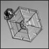
Fig. 2. Ice crystal morphology diagram illustrating the shapes (habit) of ice crystals as a function of both ambient temperature and ice supersaturation. Click on the ice crystals in the image to view one of a total of six photo galleries of crystals of that habit.Fig. 3. Expected experimental configuration of apparatus during scattering experiments. Ice crystals of the desired properties will be generated in the cloud chamber which will then fall into the motorised scattering chamber beneath. Scattering that occurs will be detected and the ice crystals will continue to fall down and through the Cloud Particle Imager where they will be detected for later analysis. Mouseover the white dots in the image to view more information.
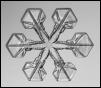
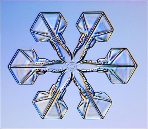
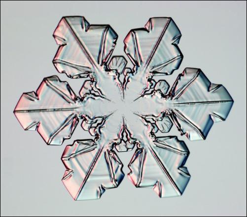
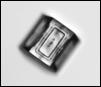
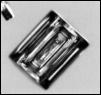
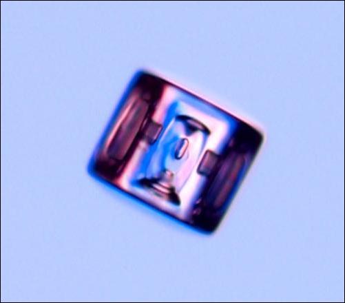
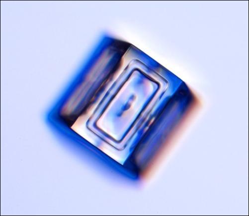
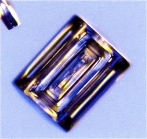
Mouseover the thumbnails to view a larger image.Images courtesy ofSnowCrystals.comwhere further reading can be found.
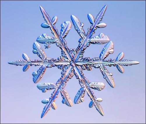
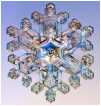
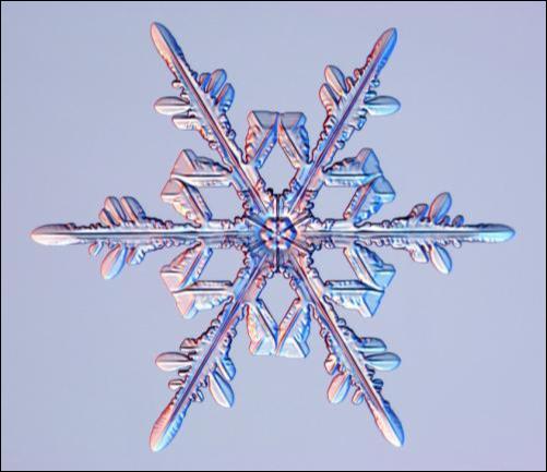
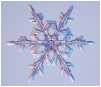
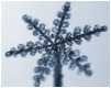
Dendrites
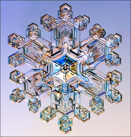
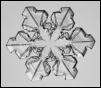
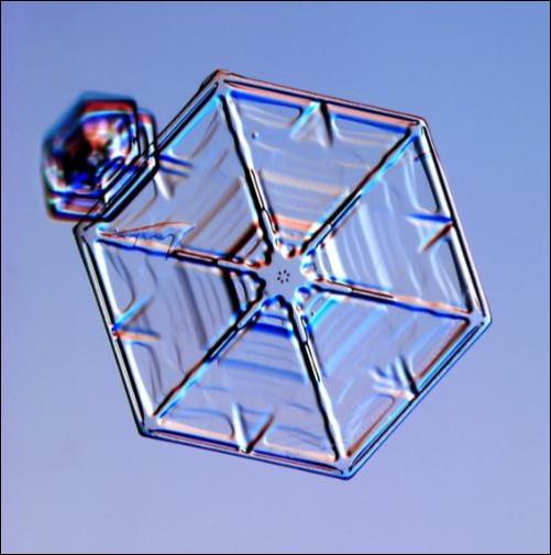
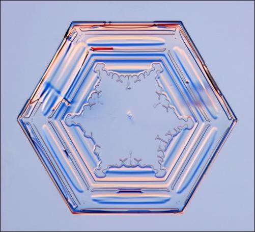
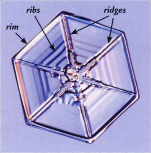
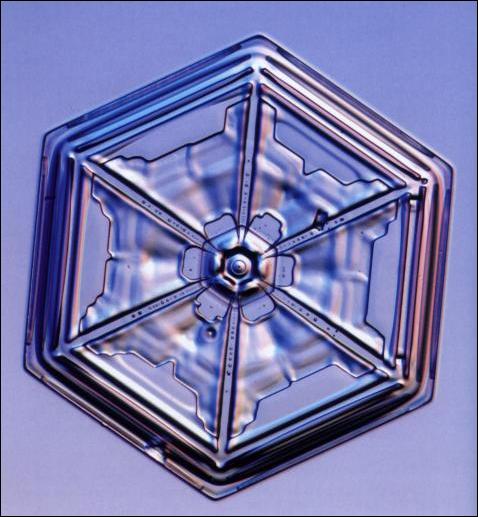
Mouseover the thumbnails to view a larger image.Images courtesy ofSnowCrystals.comwhere further reading can be found.Sectoredplates
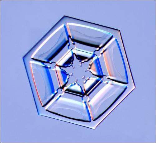
Mouseover the thumbnails to view a larger image.Images courtesy ofSnowCrystals.comwhere further reading can be found.
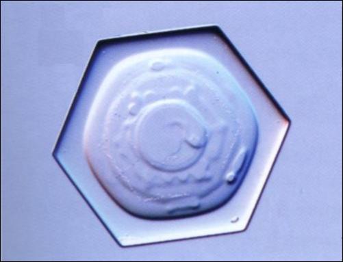
Plates
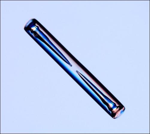
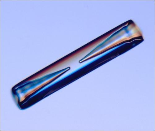
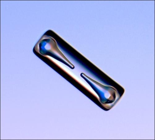
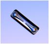
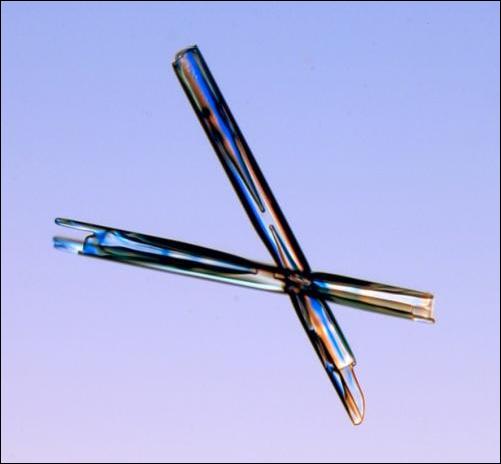
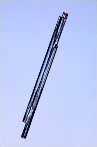
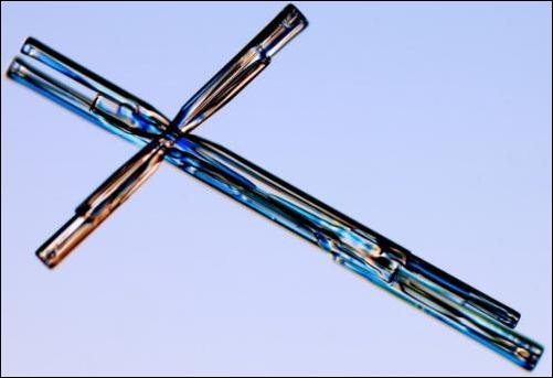
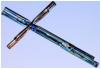
Mouseover the thumbnails to view a larger image.Images courtesy ofSnowCrystals.comwhere further reading can be found.Columns
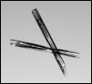
Mouseover the thumbnails to view a larger image.Images courtesy ofSnowCrystals.comwhere further reading can be found.Hollowcolumns
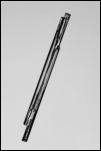
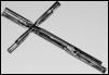
Mouseover the thumbnails to view a larger image.Images courtesy ofSnowCrystals.comwhere further reading can be found.Needles
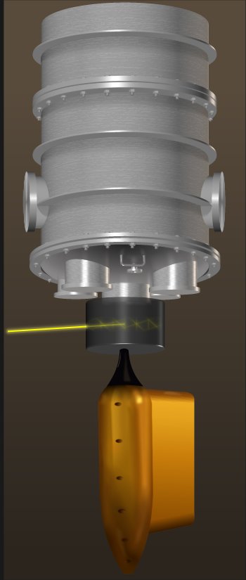
Manchester Ice Cloud ChamberIce crystals are generated, fall down to the base and into the motorised scattering chamber
Motorised scattering chamberIce crystals fall into the scattering chamber and the light source is scattered by the crystals
Cloud Particle ImagerIce crystals are imaged by this instrument for later comparisons with the scattering phase function
Light sourceLight source for the scattering chamber. A tuneable-wavelength laser is likely to be used.
Website technical factsSoftware Xara Designer Pro 6 was used to create this website and all it’s content, including graphics, panoramic photos and Flash animations. Creation involved a new approach to web design: graphical, WYSIWYG object placement without the need to code a single line of HTML or JavaScript.The site is highly optimised: the entire 19 page website consumes a grand total of just 4.5 MB, including all html, Flash, photo and graphic image files (plus there's a separate 12.6 MB of panoramic photo data—eight 50 million pixel photos). All graphics and photos are screen optimised for the web, and all this makes the site as fast as possible to load.
 M.I.C.C.
Manchester Ice Cloud Chamber
M.I.C.C.
Manchester Ice Cloud Chamber
 Light Scattering by Ice Crystals
A possible upcoming project involving the Manchester Ice Cloud Chamber (MICC) will investigate the light
scattering properties of ice crystals. As light waves strike an ice crystal, they can be deflected and travel in a
different direction. This scattering direction is not always the same, but over time, with many such light
scattering events, a general scattering pattern (scattering phase function) is produced (Fig. 1). The nature of
this pattern is determined by the ice crystal’s size and shape and also on the wavelength of incident light. The
crystal’s size and shape are in turn
determined by the environment in
which they are growing; crystals
grown at different temperatures for
example have different shapes
(habits) as shown in the morphology
diagram (Fig. 2).
An understanding of the scattering of
light by ice crystals is important in
many areas. Firstly, correctly
knowing how much of the incoming
solar radiation is reflected back into
space has important consequences
for studies of our changing climate.
Clouds containing crystals of a type
which reflect a lot of this radiation
(high albedo clouds) can contribute a
net cooling effect, acting to counter
the warming effect of the greenhouse
gases, and is therefore an important
area to understand. Knowing how
the scattering phase function varies with crystal cloud type will allow the validation of scattering models used
in climate studies.
This work is also important in the development of the use of light detection and ranging (LIDAR) technology. A
LIDAR is a form of radar which emits a beam of light into clouds of shorter wavelength (infrared, 1.5 µm) than
most conventional radars (see the Chilbolton weather website for some further reading). The beam is
scattered by the cloud particles, and what is returned is used to infer cloud properties. There is uncertainty in
the scattering signal produced by ice clouds and a better understanding of how the light is scattered by
different crystal habits will help improve the use of the technology. An additional uncertainty comes from the
use of 1.5 µm light which is readily absorbed as it travels from and back to the LIDAR through the atmosphere.
Using this wavelength in the laboratory studies can also help identify the extent that this is likely occurring in
the field.
Of particular interest in relation to studies of climate change is the effect that ice crystal aggregates have on
scattering. Studies (e.g. Connolly et al., 2005) have shown lots of aggregate particles (long chains of
connected crystals) in the anvils of thunderstorms, in particular, the aggregation of horizontally aligned plate
crystals which act like small mirrors and generate highly
reflective clouds. Such storms and associated anvils are
situated in equatorial regions, where the greatest input of
solar radiation to the Earth’s heat system occurs, and
where it is thus particularly important to understand the
scattering properties of such ice clouds. The aggregation
section of this website contains further information on
this.
The MICC facility allows the production of crystals with a
wide range of sizes and habits for examination, and
uniquely, the production of aggregate particles, thanks to
its 10 m height, which provides the fall-time for crystals to
stick together. A multi-wavelength tuneable laser will
provide a high powered light source to enhance the
scattering signal-to-noise ratio, also allowing a quick (<1
s) determination of the scattering phase functions of the
crystals. Such rapid measurements are necessary as the
properties of the cloud passing quickly through the
scattering chamber will not remain constant, e.g. particle
concentrations and size distributions will change with
time.
Experimental procedures will generally involve
generating a crystal cloud with desired properties, which
will then be introduced to a motorised scattering chamber
(Fig. 3). A light source shining into the scattering
chamber will interact with the cloud, and the resulting
scattering phase function will be measured. The
constituent cloud particles are measured with the CPI for
later comparison with the scattering phase function.
References and other reading
Connolly, P. J., C. P. R. Saunders, M. W. Gallagher, K. N. Bower, M. J.
Flynn, T. W. Choularton, J. Whiteway, and P. Lawson, 2005: Aircraft
observations of the influence of electric fields on the aggregation of ice
crystals. Quart. J. Roy. Meteor. Soc., 131, 1695–1712.
Heymsfield, A. J., and G. M. McFarquhar, 1996: High albedos of cirrus in
the tropical pacific warm pool: Microphysical interpretations from
CEPEX and from Kwajalein, Marshall Islands. J. Atmos. Sci., 53(17),
2424–2451.
McFarquhar, G. M., U. Junshik, M. Freer, D. Baumgardner, G. L. Kok, and
G. Mace, 2007: Importance of small ice crystals to cirrus properties:
Observations from the tropical warm pool international cloud experiment
(twp-ice). Geophys. Res. Lett., 34, 13,803–.
Stephens, G. L., S. Tsay, P. W. Stackhouse, and P. J. Flatau, 1990: The
relevance of the microphysical and radiative properties of cirrus clouds
to climate and climatic feedback. J. Atmos. Sci., 47, 1742–1753.
Um, J., and G. M. McFarquhar, 2009: Single-scattering properties of
aggregates of plates. Quart. J. Roy. Meteor. Soc., 135, 291–304.
Light Scattering by Ice Crystals
A possible upcoming project involving the Manchester Ice Cloud Chamber (MICC) will investigate the light
scattering properties of ice crystals. As light waves strike an ice crystal, they can be deflected and travel in a
different direction. This scattering direction is not always the same, but over time, with many such light
scattering events, a general scattering pattern (scattering phase function) is produced (Fig. 1). The nature of
this pattern is determined by the ice crystal’s size and shape and also on the wavelength of incident light. The
crystal’s size and shape are in turn
determined by the environment in
which they are growing; crystals
grown at different temperatures for
example have different shapes
(habits) as shown in the morphology
diagram (Fig. 2).
An understanding of the scattering of
light by ice crystals is important in
many areas. Firstly, correctly
knowing how much of the incoming
solar radiation is reflected back into
space has important consequences
for studies of our changing climate.
Clouds containing crystals of a type
which reflect a lot of this radiation
(high albedo clouds) can contribute a
net cooling effect, acting to counter
the warming effect of the greenhouse
gases, and is therefore an important
area to understand. Knowing how
the scattering phase function varies with crystal cloud type will allow the validation of scattering models used
in climate studies.
This work is also important in the development of the use of light detection and ranging (LIDAR) technology. A
LIDAR is a form of radar which emits a beam of light into clouds of shorter wavelength (infrared, 1.5 µm) than
most conventional radars (see the Chilbolton weather website for some further reading). The beam is
scattered by the cloud particles, and what is returned is used to infer cloud properties. There is uncertainty in
the scattering signal produced by ice clouds and a better understanding of how the light is scattered by
different crystal habits will help improve the use of the technology. An additional uncertainty comes from the
use of 1.5 µm light which is readily absorbed as it travels from and back to the LIDAR through the atmosphere.
Using this wavelength in the laboratory studies can also help identify the extent that this is likely occurring in
the field.
Of particular interest in relation to studies of climate change is the effect that ice crystal aggregates have on
scattering. Studies (e.g. Connolly et al., 2005) have shown lots of aggregate particles (long chains of
connected crystals) in the anvils of thunderstorms, in particular, the aggregation of horizontally aligned plate
crystals which act like small mirrors and generate highly
reflective clouds. Such storms and associated anvils are
situated in equatorial regions, where the greatest input of
solar radiation to the Earth’s heat system occurs, and
where it is thus particularly important to understand the
scattering properties of such ice clouds. The aggregation
section of this website contains further information on
this.
The MICC facility allows the production of crystals with a
wide range of sizes and habits for examination, and
uniquely, the production of aggregate particles, thanks to
its 10 m height, which provides the fall-time for crystals to
stick together. A multi-wavelength tuneable laser will
provide a high powered light source to enhance the
scattering signal-to-noise ratio, also allowing a quick (<1
s) determination of the scattering phase functions of the
crystals. Such rapid measurements are necessary as the
properties of the cloud passing quickly through the
scattering chamber will not remain constant, e.g. particle
concentrations and size distributions will change with
time.
Experimental procedures will generally involve
generating a crystal cloud with desired properties, which
will then be introduced to a motorised scattering chamber
(Fig. 3). A light source shining into the scattering
chamber will interact with the cloud, and the resulting
scattering phase function will be measured. The
constituent cloud particles are measured with the CPI for
later comparison with the scattering phase function.
References and other reading
Connolly, P. J., C. P. R. Saunders, M. W. Gallagher, K. N. Bower, M. J.
Flynn, T. W. Choularton, J. Whiteway, and P. Lawson, 2005: Aircraft
observations of the influence of electric fields on the aggregation of ice
crystals. Quart. J. Roy. Meteor. Soc., 131, 1695–1712.
Heymsfield, A. J., and G. M. McFarquhar, 1996: High albedos of cirrus in
the tropical pacific warm pool: Microphysical interpretations from
CEPEX and from Kwajalein, Marshall Islands. J. Atmos. Sci., 53(17),
2424–2451.
McFarquhar, G. M., U. Junshik, M. Freer, D. Baumgardner, G. L. Kok, and
G. Mace, 2007: Importance of small ice crystals to cirrus properties:
Observations from the tropical warm pool international cloud experiment
(twp-ice). Geophys. Res. Lett., 34, 13,803–.
Stephens, G. L., S. Tsay, P. W. Stackhouse, and P. J. Flatau, 1990: The
relevance of the microphysical and radiative properties of cirrus clouds
to climate and climatic feedback. J. Atmos. Sci., 47, 1742–1753.
Um, J., and G. M. McFarquhar, 2009: Single-scattering properties of
aggregates of plates. Quart. J. Roy. Meteor. Soc., 135, 291–304.
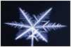
 Fig. 1. Illustration of the formation of a scattering phase function by the presence
of an ice crystal. Light striking the crystal is preferentially scattered in different
directions—some more favourably than others depending on crystal properties
and wavelength of light. The animated illustration can be navigated using the
displayed control buttons.
Site and content created using Xara Designer Pro 6
Fig. 1. Illustration of the formation of a scattering phase function by the presence
of an ice crystal. Light striking the crystal is preferentially scattered in different
directions—some more favourably than others depending on crystal properties
and wavelength of light. The animated illustration can be navigated using the
displayed control buttons.
Site and content created using Xara Designer Pro 6


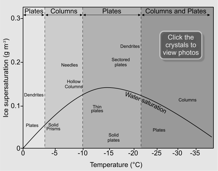 Fig. 2. Ice crystal morphology diagram illustrating the shapes (habit) of ice crystals as a function of both ambient temperature and
ice supersaturation. Click on the ice crystals in the image to view one of a total of six photo galleries of crystals of that habit.
Fig. 2. Ice crystal morphology diagram illustrating the shapes (habit) of ice crystals as a function of both ambient temperature and
ice supersaturation. Click on the ice crystals in the image to view one of a total of six photo galleries of crystals of that habit.

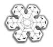


 Fig. 3. Expected experimental configuration of
apparatus during scattering experiments. Ice crystals of
the desired properties will be generated in the cloud
chamber which will then fall into the motorised
scattering chamber beneath. Scattering that occurs will
be detected and the ice crystals will continue to fall
down and through the Cloud Particle Imager where they
will be detected for later analysis. Mouseover the white
dots in the image to view more information.
Fig. 3. Expected experimental configuration of
apparatus during scattering experiments. Ice crystals of
the desired properties will be generated in the cloud
chamber which will then fall into the motorised
scattering chamber beneath. Scattering that occurs will
be detected and the ice crystals will continue to fall
down and through the Cloud Particle Imager where they
will be detected for later analysis. Mouseover the white
dots in the image to view more information.